Punching reinforcement
Punching reinforcement
When you select Punching reinforcement in Manual design, the tool opens a dropdown with five punching detailing approaches.
![]()
You can use these approaches to place and edit reinforcement around punching regions with mode-specific geometry and detailing parameters.
Design approaches
-
Stud rail, general product – place stud rails with a generic product definition.
-
Stud rail, PEIKKO PSB product – place stud rails with PEIKKO PSB-specific options.
-
Banded bar – place bent bar reinforcement for punching.
-
Circular stirrup – place circular stirrup links with optional auxiliary bars.
-
Open stirrup – place open stirrup links in user-defined reinforcement regions.
Tool palette
Each punching approach opens a tool palette with the same main tool group, but additional tool, definition methods and default settings specific to the selected approach.
Main tools
-
Define – create new punching reinforcement using the active approach.
-
Properties – inspect or edit existing punching reinforcement. Opens the same settings dialogue as Default settings for selected objects.
-
Default settings – define default parameters used when placing new punching reinforcement.
Stud rail, general product
Additional settings on tool palette

-
Radial – radio button for radial rail distribution.
-
Orthogonal – radio button for orthogonal rail distribution.
-
Semi-orthogonal – radio button for semi-orthogonal rail distribution.
-
n rail (on full circle) – numeric field for number of rails around a full circle.
-
n stud – numeric field for number of studs per rail.
-
Auto set s0/r1 by punching – checkbox for automatic calculation of spacing values from punching conditions.
-
s0 – numeric field for the first stud spacing.
-
s1 – numeric field for the second stud spacing.
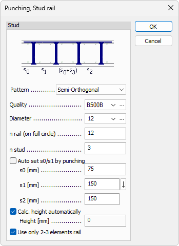
Stud rail, general product default settings
-
Pattern – dropdown with Radial, Orthogonal, and Semi-orthogonal.
-
Quality – reinforcement steel quality dropdown with Edit library support.
-
Diameter – stud diameter dropdown with Edit library support.
-
n rail (on full circle) – numeric field for default number of rails.
-
n stud – numeric field for default number of studs per rail.
-
Auto set s0/s1 by punching – checkbox for automatic s0 and s1 values.
-
s0 – numeric field for first spacing.
-
s1 – numeric field for second spacing.
-
s2 – numeric field for third spacing.
-
Calc. height automatically – checkbox for automatic stud rail height.
-
Height – numeric field for manual height; available only when automatic height is disabled.
-
Use only 2-3 elements rail – checkbox that limits generated rails to 2-3 element rails.
Stud rail, PEIKKO PSB product
This approach is similar to Stud rail, general product, with one additional option in the tool palette.
Additional setting on tool palette
- PSB PLUS – checkbox for activating the PSB PLUS solution.
Stud rail, PEIKKO PSB product default settings
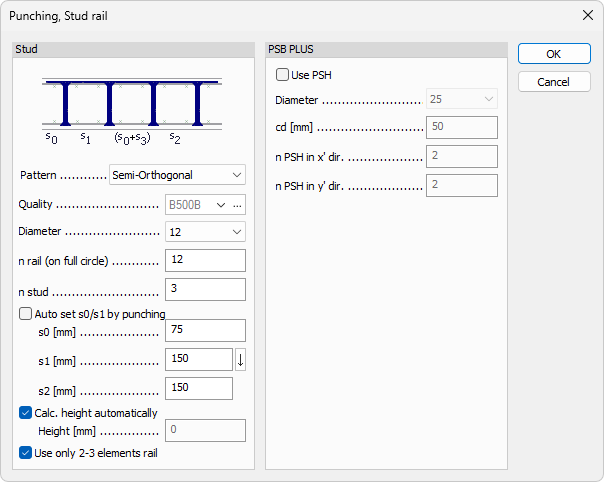
This dialogue includes all settings from Stud rail, general product default settings, plus a dedicated PSB PLUS group.
PSB PLUS group
-
Use PSH – checkbox that enables PSH usage.
-
Diameter – dropdown with predefined PSH diameter values.
-
cd – numeric field.
-
n PSH in x' dir. – numeric field for number of PSH elements in local x' direction.
-
n PSH in y' dir. – numeric field for number of PSH elements in local y' direction.
Bended bar
Uses bended bars placed around the punching region as reinforcement.
Additional functions on tool palette

-
Parallel with axis x' – align the bended bar layout parallel to local x' axis.
-
Parallel with axis y' – align the bended bar layout parallel to local y' axis.
Bended bar default settings

-
Quality – reinforcement steel quality dropdown with Edit library support.
-
Diameter – bar diameter dropdown with Edit library support.
-
alpha – numeric field for bend angle.
-
h – numeric field for bent bar height.
-
l1 – numeric field for the middle section length.
-
l2 – numeric field for each outer section length.
Circular stirrup
Circular stirrup links are placed around the punching region, with optional auxiliary bars between them. The tool palette has only the main tool group and no additional functions.
Circular stirrup default settings

The default settings dialogue is divided into two groups: Stirrup and Auxiliary.
Stirrup group
-
Quality – reinforcement steel quality dropdown with Edit library support.
-
Diameter – stirrup diameter dropdown with Edit library support.
-
w – numeric field for stirrup link width.
-
h – numeric field for stirrup link height.
-
Max. distance – numeric field for maximum stirrup distance.
Auxiliary group
-
Quality – reinforcement steel quality dropdown with Edit library support.
-
Diameter – auxiliary bar diameter dropdown with Edit library support.
-
Overlap – numeric field for overlap length.
Open stirrup
Open stirrup links are placed in user-defined regions around the punching area. The tool palette includes additional region definition methods.
Define region methods on tool palette

-
Rectangular – define a rectangular punching reinforcement region.
-
Circular – define a circular punching reinforcement region.
-
Polygonal – define a polygonal punching reinforcement region.
-
Pick lines – define a region by selecting existing lines.
-
Pick existing region – reuse an existing region definition.
Open stirrup default settings

-
Quality – reinforcement steel quality dropdown with Edit library support.
-
Diameter – stirrup diameter dropdown with Edit library support.
-
w – numeric field for stirrup link width.
-
h – numeric field for stirrup link height.
-
l – numeric field for stirrup link bottom section length.
-
dx – numeric field for spacing between stirrup-link rows (center-to-center).
-
dy – numeric field for spacing between stirrup links within one row.