Calculation parameters
Calculation parameters tool is used to set the design and detailing parameters for concrete elements. The parameters are specific for the selected subtype of design and are used in the design calculations for auto design.
![]()
When you select the tool then you need to select the element for which you want to set the design parameters. After selecting the element, the calculation parameters dialogue will open. The dialog depends on the selected subtype of design and contains different parameters for different subtypes.
Parameters for bar design
Calculation parameters tool opens a dialogue that has two tabs: General and Fire.
General parameters for bar design
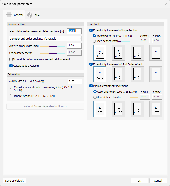
General settings
-
Max. distance between calculated sections – numeric input for the maximum spacing between cross-sections evaluated during design
-
2nd order analysis – drop-down menu to select how second-order effects are handled in the design:
-
Ignore 2nd order analysis – second-order effects are not considered
-
Consider 2nd order analysis, if available – second-order effects are included when 2nd order analysis results exist
-
2nd order internal forces + 1st order design – second-order internal forces are used together with a first-order design approach
-
-
Allowed crack width – numeric input for the maximum permitted crack width
-
Crack safety factor – numeric input for the partial safety factor applied to crack width calculations
-
If possible do not use compressed reinforcement – checkbox to avoid placing compression reinforcement when it is not structurally necessary
-
Calculate as a Column – checkbox to treat the bar element as a column for design purposes
Calculation
-
cot(θ) (EC2 1-1: 6.2.3 (6.8)) – numeric input for the shear strut inclination factor according to EN 1992-1-1 clause 6.2.3
-
Consider moments when calculating λ lim (EC2 1-1: 5.13N) – checkbox to include bending moments when determining the slenderness limit λ lim
-
Ignore torsion (EC2 1-1: 6.3.1 (2)) – checkbox to exclude torsion from the design according to EN 1992-1-1 clause 6.3.1
-
National Annex dependent options – expandable section containing parameters that vary depending on the selected National Annex
Eccentricity
Eccentricity increment of imperfection
-
Eccentricity increment of imperfection – checkbox to activate the eccentricity increment of imperfection and the related settings; when activated, the eccentricity increment is added to the design eccentricity to account for imperfections in the structure.
-
According to EN 1992-1-1: 5.8 – option to calculate the imperfection eccentricity from the standard
-
User-defined – option to override the standard-derived values with manual inputs:
- e impf1 – imperfection eccentricity in direction 1
- e impf2 – imperfection eccentricity in direction 2
Eccentricity increment of 2nd Order effect
-
Eccentricity increment of 2nd Order effect – checkbox to activate the eccentricity increment from second-order effects
-
Direction selection – graphical control to select the direction in which the 2nd order eccentricity increment is applied
Minimal eccentricity increment
You can specify the minimal eccentricity increment based on the standard or as a user-defined value.
-
According to EN 1992-1-1: 6.1 (4) – option to calculate the minimal eccentricity from the standard; the following read-only fields show the derived values:
-
e min1 – minimal eccentricity in direction 1
-
e min2 – minimal eccentricity in direction 2
-
-
User-defined – option to override the standard-derived values with manual inputs:
- e0 / e0 – two numeric input fields for entering user-defined minimal eccentricities in each direction
Bottom actions
- Save as default – saves the current settings as the default values for new elements