Draw reinforcement
Use Draw reinforcement to manually place reinforcement on supported concrete objects. Use this tool when you want direct geometric control over the reinforcement layout.
This tool is only available for bar-type elements.
![]()
Tool palette
When you start the tool, a tool palette opens.

- Calculation – select which load combinations or load groups to use during manual design.
After that, you select a bar element in the model where you want to start modeling reinforcement.
Reinforced bar manual design mode
When you select suitable element FEM-Design then opens a dedicated manual design mode for reinforced bars.
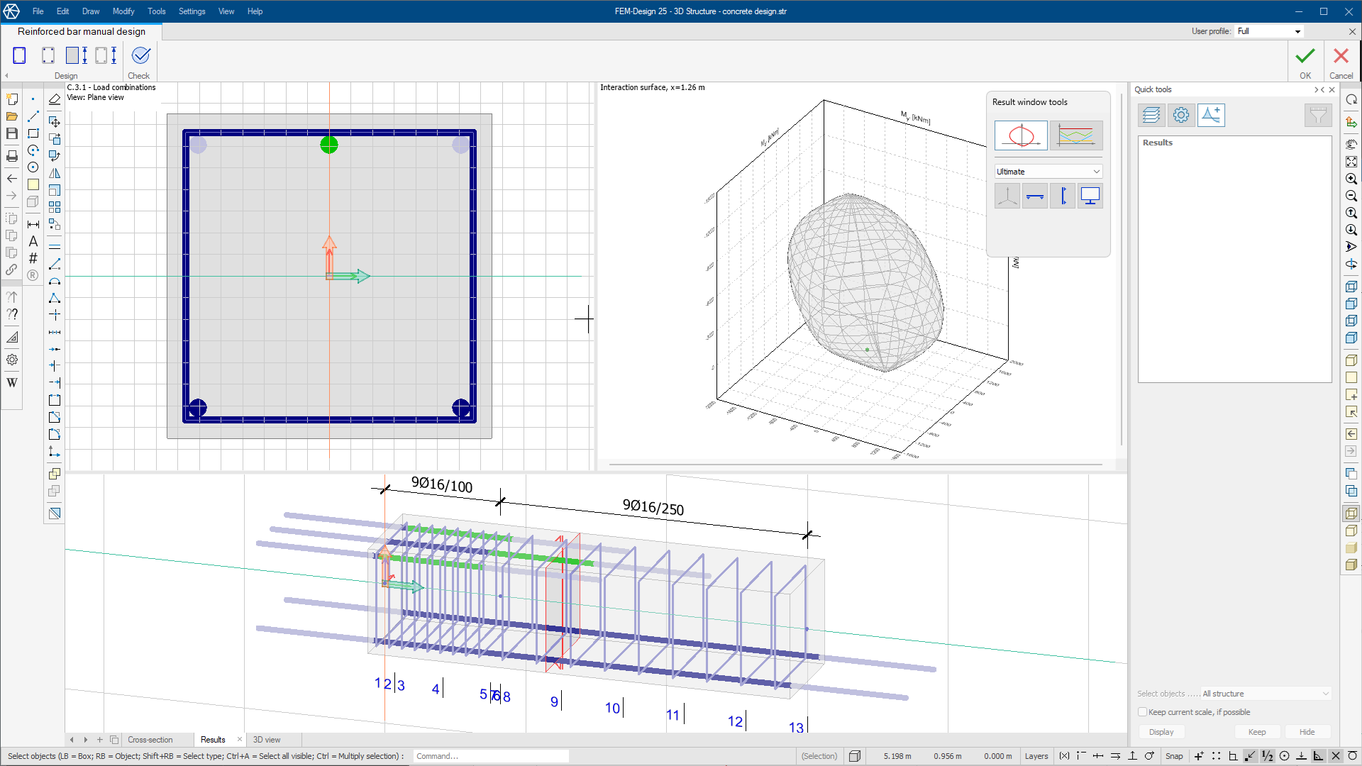
Overview
The mode opens three graphical windows that you use together:
-
Cross-section – section-based reinforcement editing and review.
-
Results – interaction surface and summary-based check feedback.
-
3D view – side-oriented 3D view by default, with free rotation.
A typical workflow is to add reinforcement in the section view, define start and end graphically in the side view, and monitor the effect in the interaction surface.
This mode uses a dedicated ribbon tab named Reinforced bar manual design. Some general viewing and editing tools are still available, but the design workflow is focused on this tab.
The tab contains two panels:
-
Design – contains tools for creating and modifying reinforcement.
-
Stirrup – place and edit stirrups.
-
Longitudinal bar – place and edit longitudinal reinforcement bars.
-
Applied section – change the active cross-section without leaving manual design mode.
-
Parametric reinforcement – open the parametric reinforcement dialog for RC bars.
-
-
Check – runs design checks for the current manual setup.
On the right side of the ribbon, use:
-
OK – apply the drawn or edited reinforcement.
-
Cancel – close the mode without applying changes. Any previously applied manual or automatic design remains unchanged.
Stirrup
The Stirrup tool opens a tool palette.

Main tools
-
Define – choose how the stirrup region is defined.
-
Properties – set geometric and bar distribution parameters during placement. Opens a Default settings dialoge for the selected stirrup
-
Default settings – set default stirrup material and geometric values (read below in more detail).
Line definition methods
Only available when Define is selected.
-
Rectangular – define a rectangular stirrup region.
-
Circular – define a circular stirrup region.
-
Polygonal – define a polygonal stirrup region.
-
Pick lines – create a region by selecting existing lines.
-
Pick existing region – reuse an existing region definition.
Settings
-
Diameter – bar diameter list with library editing support.
-
Distance – spacing value.
-
Cover – concrete cover value.
-
Alignment – select whether stirrups are placed relative to the drawn line as outer or inner.
Stirrup Default settings
When you select the Default settings tool, a new dialogue opens.

-
Quality – bar quality list with library editing support.
-
Diameter – default diameter with library editing support.
-
Profile – select ribbed or smooth profile.
-
Distance – default spacing value.
Longitudinal bar
The Longitudinal bar tool opens a tool palette.

Main tools
-
Define – choose the drawing method for bars.
-
Properties – set dimensions, anchorage, and group layout values. Opens a Default settings dialog for the selected bars.
-
Default settings – set default bar material and anchorage properties (read below in more detail).
Line definition methods
Only available when Define is selected.
-
Single bar – place one bar at a time.
-
Group of bars – place a bar group with array-style layout parameters.
For Group of bars, drawing tools include:
-
Straight line – draw bars along a straight segment.
-
Arc by center, start point and angle – define an arc from center-based input.
-
Arc by 3 points – define an arc from three picked points.
-
Arc by start-end point and tangent – define an arc from geometric boundary and tangent conditions.
-
Line by selection – use an existing selected line as the path.
Settings
-
Diameter – bar diameter list with library editing support.
-
Start anch. – start anchorage length.
-
End anch. – end anchorage length.
-
Nc – number of columns in a group.
-
Nr – number of rows in a group.
-
C – distance between rows.
Longitudinal bar Default settings
When you select the Default settings tool, a new dialog opens.

-
Quality – bar quality list with library editing support.
-
Diameter – default diameter with library editing support.
-
Profile – select ribbed or smooth profile.
-
Start anchorage – default start anchorage value.
-
End anchorage – default end anchorage value.
-
Auxiliary bar – include bar as auxiliary reinforcement.
Applied section
Applied section opens the Select cross-section dialog, where you can choose a new section from the section library.
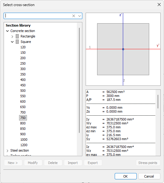
This lets you change section shape directly in manual design mode without leaving the workflow.
To read more about the section library and how to manage sections, see the topic:
User interface ➔ Tab menus ➔ Structure ➔ Additional dialogues ➔ Bar Section
Parametric reinforcement
Parametric reinforcement opens the RC bar parametric reinforcement dialog.
Use this when you want to apply reinforcement by parametric definition instead of drawing each part manually.
To read more about the parametric reinforcement, see the topic:
User interface ➔ Tab menus ➔ Concrete Design ➔ Manual Design ➔ Parametric Reinforcement
Check
The Check tool runs design checks only.
It does not open a dedicated tool palette or utilization window. Instead, it uses the Results window to show the check results.
Results view
The Results window has its own tool palette controlling what is displayed.
It has two main display modes:
-
Interaction surface – visualizes load and capacity interaction.
-
Summary – shows utilization over the bar length for selected checks.
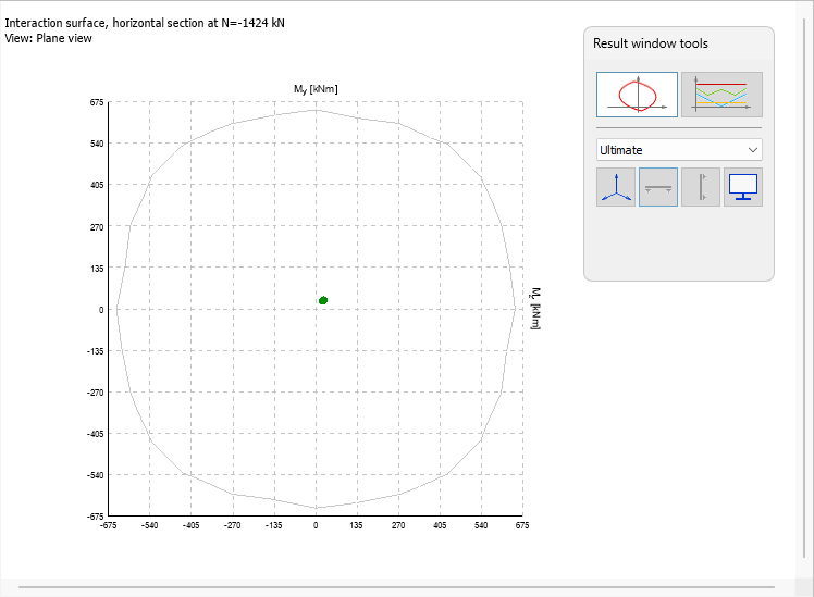
Interaction surface
When you select Interaction surface from the tool palette, the view shows the interaction surface for the current section and reinforcement setup.
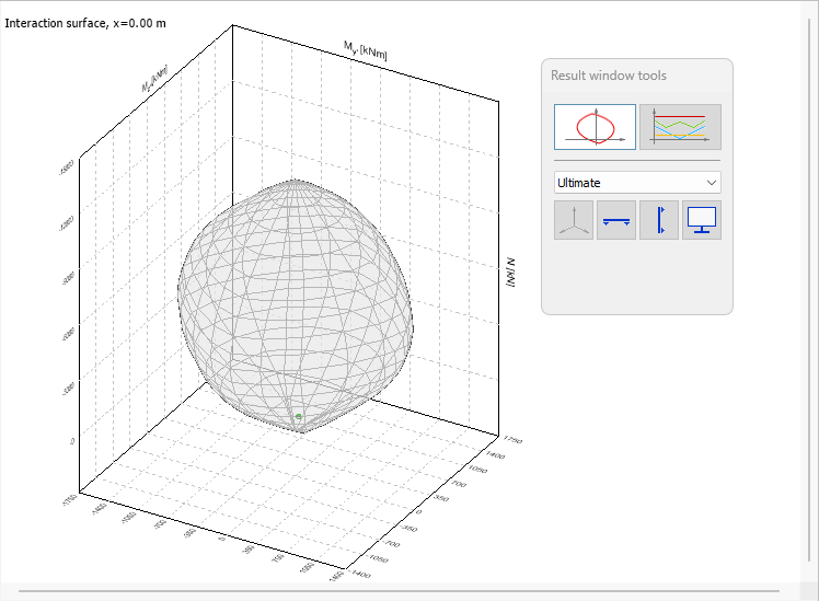
Tool palette
In the active tool palette, you can choose which interaction surface to display.
This mode includes a drop-down list for the load combination or load group type, for example Ultimate or Accidental/Seismic.
Below the drop-down are the following buttons:
-
Return to 3D view – selected by default; returns to a freely rotatable 3D interaction surface view.
-
Horizontal cut – define a horizontal plane on the 3D interaction surface and view the 2D cut.
-
Vertical cut – define a vertical plane on the 3D interaction surface and view the 2D cut.
-
Display options – open display settings for interaction scaling and section-view force tolerances.
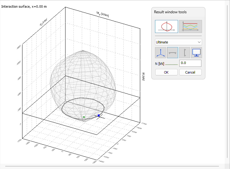
Horizontal and vertical cut
When you select either Horizontal cut or Vertical cut, you can use the mouse to define the plane, and the view changes to a 2D cut defined by the selected plane.
Display options
When you select Display options, a new dialog opens.

Interaction surface scaling**
- Auto calculate – automatically calculates the scaling based on the current section and reinforcement setup
- User defined M/N ratio – enables a numeric ratio field for manual scaling
Tolerance for internal forces in section view
Set numeric tolerances for horizontal and vertical sections.
Summary
This mode shows utilization graphs along the bar length.
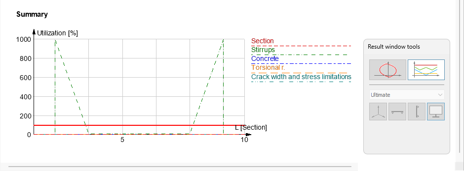
-
Section – section utilization.
-
Stirrups – stirrup-related utilization.
-
Concrete – concrete utilization.
-
Torsional reinforcement – torsion-related reinforcement utilization.
-
Crack width and stress limitations – serviceability-related checks.
3D view
The 3D view opens as a side-oriented view by default, and you can rotate it freely.
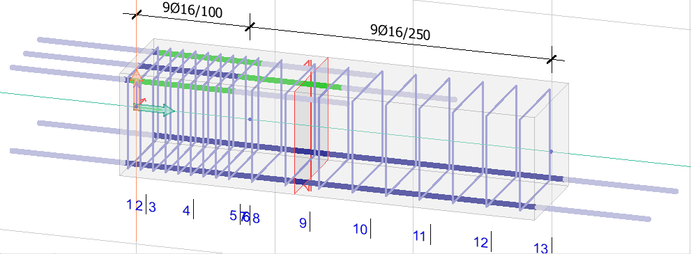
The view shows both applied stirrups and longitudinal bars.
For stirrups, the view shows the stirrup region length and a stirrup formula, for example 9Ø16/100.
For longitudinal bars, the view shows:
-
Dark blue – active fully anchored bar that participates in design calculations.
-
Light blue – anchorage part that does not participate in calculations.
-
Green – shear lengthening part.
The red section symbol inside the bar element marks the location where the 2D section view is generated. The symbol can be moved with regular moving methods to see different sections.
Under the bar element, characteristic calculation sections are marked with numbers.