Manual design
Manual design
Manual design is used to apply manual design settings to steel elements. The workflow and available options depend on the selected steel design subtype.
![]()
Steel bar and Steel bar, fire design subtypes
When Manual design is activated for these subtypes, a tool palette opens.

Tool palette
-
Define – apply manual design to selected elements.
-
Properties – view or modify manual design settings of selected elements.
-
Default settings – open default manual-design settings for the selected subtype.
Additional settings:
-
Calculation – drop-down menu with Load combinations and Load groups.
-
Display table – checkbox that shows the utilization table.
Special setting for Steel bar subtype:
- Section – drop-down list of sections available in the model.
Default settings dialogue
The Default settings dialogue depends on selected subtype.
Steel bar subtype:
Opens section library selection, following the main section-library logic.
To read more about section library and section selection, see:
User interface -> Tab menus -> Structure -> Additional dialogues -> Bar Section
Steel bar, fire design subtype:
Opens a fire protection dialogue.

This dialogue has two main options:
- Apply fire protection material
- Set temperature
When Apply fire protection material is selected, these options are available:
-
Material – drop-down with Edit library function, same logic as in steel auto design.
-
Thickness – numeric field.
When Set temperature is selected, this option is available:
- Maximum member temperature – numeric field.
to read more about fire protection materials and temperature settings, see:
User interface ➔ Tab menus ➔ Steel design ➔ Auto design
Utilization table
When Display table is enabled, a utilization table opens similarly to the auto design workflow.
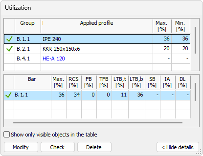
The table allows you to review utilization and update selected manual design quantities.
To read more about utilization table, see the Check tool article:
User interface ➔ Tab menus ➔ Steel design ➔ Check
Table options and buttons
The bottom part always contains:
-
Show only visible objects in the table – limits rows to currently visible model objects.
-
Modify – opens the Default settings dialogue for selected row.
-
Check – runs design check for selected table row.
-
Delete – deletes applied design quantity for selected row.
Steel bar, shell model subtype
For this subtype, Manual design prompts you to select a steel bar shell in model view.
After selection, a small dialogue opens with one option:

- Applied thickness
Steel joint subtype
For this subtype, Manual design prompts you to select a defined steel joint in model view.
After selection, FEM-Design switches to a dedicated user-interface mode for steel-joint manual design.
To read more about steel joint manual design, see:
User interface ➔ Tab menus ➔ Steel design ➔ Steel joint