Steel joint
Steel joint design mode opens a dedicated workspace for focused joint design.
In this workspace, you define and verify steel joint solutions with live geometry and calculation feedback.
Open Steel joint mode
There are two ways to open Steel Joint mode:
- built-in mode – select a steel joint in the model and click Manual design to open steel joint mode for that joint context.
- stand-alone mode – open the mode from the FEM-Design Command Center to work in a stand-alone steel joint mode.
The same tools are available in both entry points, but the workflow scope is different.
-
global model scope – you can design only joints that are compatible with the joint definition already present in the global model.
-
stand-alone scope – you can design any available steel joint type without being limited by a specific global model joint, but all the section parameters and load combinations must be defined manually.
Overview
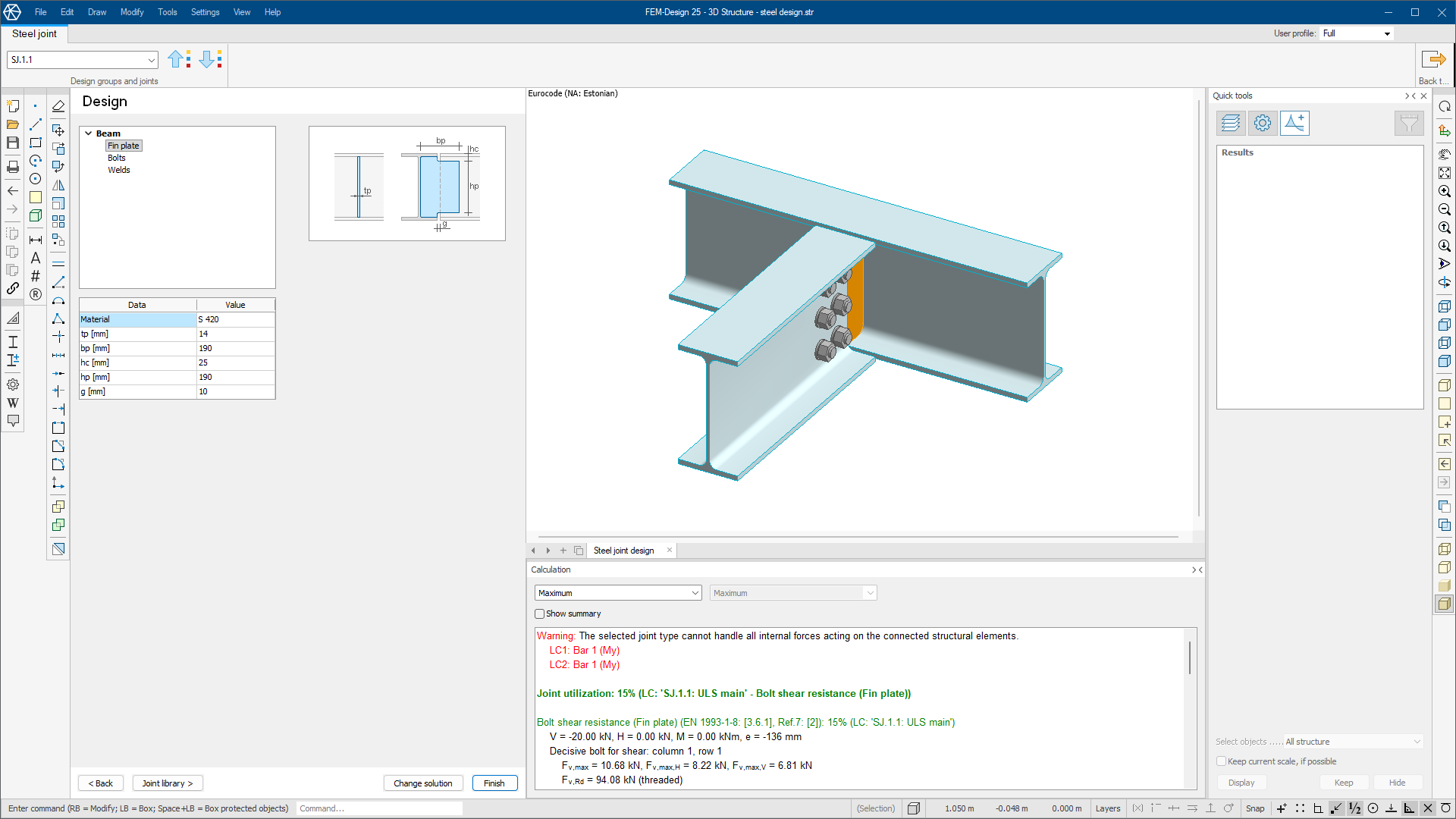
Steel Joint mode is organized into three main working sections and a dedicated ribbon tab.
-
Data/Design – defines the joint parameters, solution settings, and design input values.
-
3D view – shows the current joint geometry so you can inspect the model while you edit parameters.
-
Calculation – displays live design check results, utilization, and referenced formulas.
This mode uses a dedicated ribbon tab named Steel joint. Some general viewing and editing tools are still available, but the design workflow is focused on this tab.
The tab contains one panel named Design groups and joints.
-
Joint drop-down – lists available steel joint names in the current group from the model context.
-
Previous joint – moves to the previous joint in the same group list.
-
Next joint – moves to the next joint in the same group list.
On the right side of the ribbon use:
- Back to model – (only available in the built-in mode) exit Steel Joint mode, return to the regular model view, and apply your changes
Data/Design
The Data/Design area is divided into multiple pages.
-
< Back and Next > – page navigation buttons at the bottom of each page to move through the workflow
-
Joint library > – opens a small menu with Load, Save, and Edit so you can manage steel joint library entries
-
Finish – appears on relevant pages and applies your modifications so the joint can be saved and used in the model
-
Change solution – opens a menu of available joint solutions so you can switch the current solution type
For more details about library management dialogue and available joint solutions dialogue, see the topic:
User interface ➔ Tab menus ➔ Steel design ➔ Additional design tools ➔ Define joint
Available pages depend on the selected steel joint solution, but they generally include:
-
Data – contains basic joint information, linked cross-sections from the global model, internal forces from global analysis, and optional manual load combinations.
-
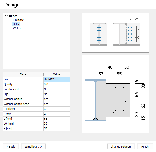
Design – contains design parameters such as plate thickness and material, bolt diameter and class, bolt quantity, and weld sizes.
3D View
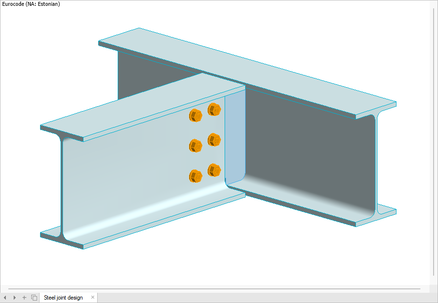
The 3D view displays the steel joint geometry, including connected members, plates, bolts, and welds.
-
Interactive inspection – rotate, zoom, and pan to review details from different angles.
-
Live geometry updates – changes from Data/Design are reflected in real time.
-
Active part highlighting – elements currently edited in Design are highlighted in orange to help you focus on the active component.
Calculation
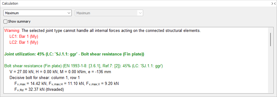
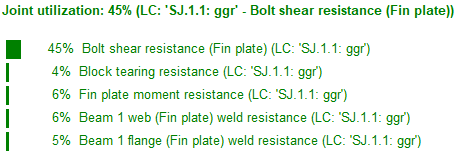
The Calculation section shows real-time analysis and design check feedback for the joint. It displays utilization results for the joint and components, with referenced formulas and uses live updates when you change design parameters.
-
Group members – use the drop-down to view either the maximum result in the group or a specific joint by name.
-
Load selection – (only when a specific joint is selected from the Group members drop-down) use this drop-down to select a load combination and see the results for that specific load combination
-
Show summary – enables a compact summary in the joint utilization paragraph in the Calculation window.