Configure design
Configure design
Configure foundation design tool in the Foundation design tab allows you to set up design settings used for foundation element checks.

When you select the Configure foundation design tool, the Foundation Design configuration dialog opens.
The dialog contains four tabs: Design approach, Safety factors, Load combinations, and Settlements.
Design approach

Select one of three design approaches as defined in EN 1997-1 2.4.7.3.4:
- 1 – A1 + M1 + R1 and A2 + M2 + R1
- 2 – A1 + M1 + R2
- 3 – (A1* + A2+) + M2 + R3
Safety factors
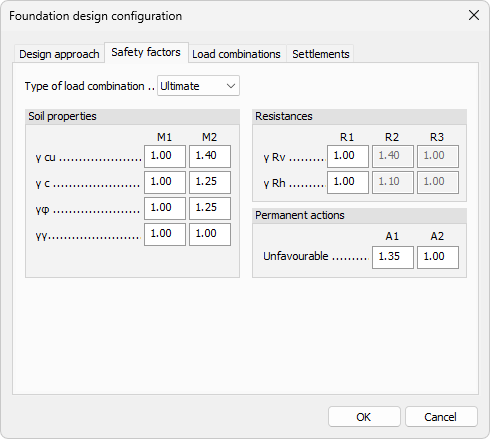
- Type of load combination – drop-down menu to select the load combination type for which the safety factors apply (e.g. Ultimate).
Soil properties
Partial factors for soil properties, defined per set M1 and M2:
- γ cu – partial factor for undrained shear strength.
- γ c – partial factor for effective cohesion.
- γΦ – partial factor for angle of shearing resistance.
- γγ – partial factor for weight density.
Resistances
Partial factors for resistances, defined per set R1, R2, and R3:
- γ Rv – partial factor for vertical bearing resistance.
- γ Rh – partial factor for horizontal sliding resistance.
Permanent actions
Partial factors for permanent actions, defined per set A1 and A2:
- Unfavourable – partial factor for unfavourable permanent actions.
Load combinations

The Load combinations tab lists the load combinations available for foundation design checks.
The table contains the following columns:
- Name – name of the load combination.
- Type – type identifier of the load combination (e.g. U for Ultimate).
- Limit state – limit state category assigned to the load combination (e.g. STR, GEO 1).
Settlements
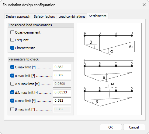
Considered load combinations
Select which load combination types are used for settlement checks:
- Quasi-permanent – checkbox to include quasi-permanent load combinations.
- Frequent – checkbox to include frequent load combinations.
- Characteristic – checkbox to include characteristic load combinations.
Parameters to check
Enable individual settlement criteria and set their limiting values:
- Θ max limit – checkbox and numeric field for the maximum tilt angle limit.
- α max limit – checkbox and numeric field for the maximum slope angle limit.
- Δs max limit – checkbox and numeric field for the maximum differential settlement limit.
- Δ/L max limit – checkbox and numeric field for the maximum relative deflection ratio limit.
- ω max limit – checkbox and numeric field for the maximum rotation angle limit.
- β max limit – checkbox and numeric field for the maximum angular distortion limit.