Parametric reinforcement
Parametric reinforcement
Use Parametric reinforcement to define manual reinforcement rules for selected composite column elements before placing or adjusting reinforcement. This function gives you control over how reinforcement is generated and updated.
This tool is only available for the Composite column subtype.

Tool palette
When you start Parametric reinforcement, a tool palette opens for defining or updating reinforcement rules for selected elements.

Main tools
-
Define – apply the current parametric reinforcement settings to selected composite column elements
-
Properties – check or edit properties of existing parametric reinforcement setups. Opens the Default settings dialogue for selected regions
-
Default settings – open the default settings dialogue to define reinforcement rules and values used by the tool (read below in more detail)
Additional functions
-
Rectangular bar – set the reinforcement mode for rectangular bar sections
-
Circular bar – set the reinforcement mode for circular bar sections
Default settings dialogue
When you open Default settings or Properties, the same dialogue window opens.
This dialogue contains three tabs: General, Stirrups, and Longitudinal bars.
Parameters in this dialogue window depend on the selected bar type. Composite column elements only support column-type detailing, so there is no beam-like reinforcement option, unlike the equivalent concrete design dialogue.
Rectangular bar settings
General tab
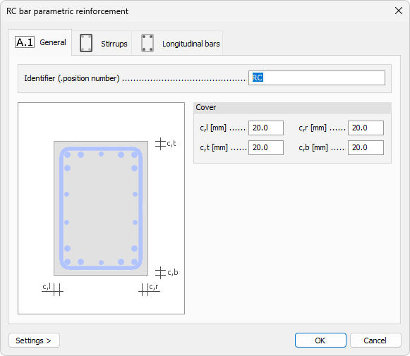
- Identifier – text field for a user-defined reinforcement setup name
Cover
-
c,l – numeric field for left concrete cover
-
c,r – numeric field for right concrete cover
-
c,t – numeric field for top concrete cover
-
c,b – numeric field for bottom concrete cover
Stirrups tab
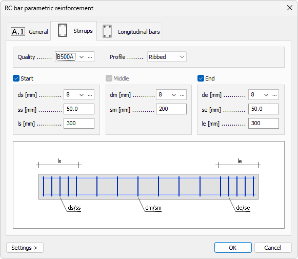
The Stirrups tab is organized into a top part, a middle part, and a bottom schematic representation.
Top part
-
Quality – drop-down menu for stirrup steel quality, with an Edit library button next to it
-
Profile – drop-down menu with Ribbed and Smooth options
Middle part
The middle part is split into Start, Middle, and End zones.
-
Start / End – checkboxes for enabling or disabling the start and end zones; the Middle zone is always active
-
ds / dm / de – diameter drop-down menus for start, middle, and end zones, each with an Edit library button
-
ss / sm / se – numeric fields for stirrup spacing in start, middle, and end zones
-
ls / le – numeric fields for start and end zone lengths; the middle zone length is defined by the remaining bar length between start and end zones
Bottom part
Contains a schematic bar view showing dimensional designators used in the tab
Longitudinal bars tab
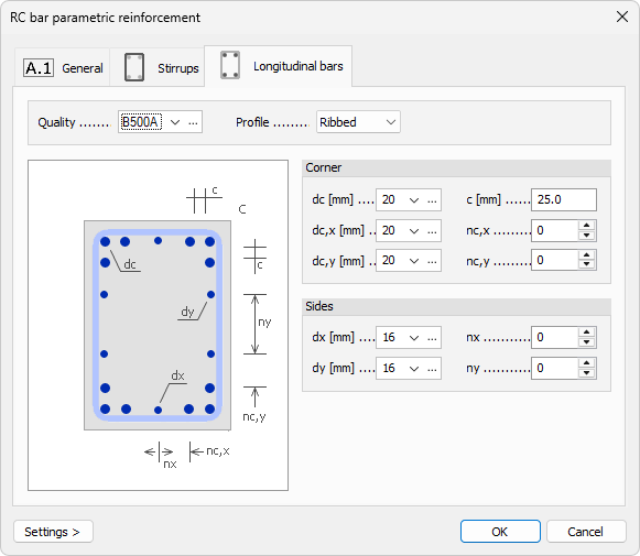
Top part
-
Quality – drop-down menu for longitudinal bar steel quality, with an Edit library button
-
Profile – drop-down menu with Ribbed and Smooth options
Corner
-
dc – drop-down menu for corner bar diameter, with an Edit library button
-
dc,x – drop-down menu for bar diameter on the x-direction side, with an Edit library button
-
dc,y – drop-down menu for bar diameter on the y-direction side, with an Edit library button
-
c – numeric field for distance between corner bars
-
nc,x – numeric field for number of bars on the x-direction side
-
nc,y – numeric field for number of bars on the y-direction side
Sides
-
dx – drop-down menu for side bar diameter in x-direction, with an Edit library button
-
dy – drop-down menu for side bar diameter in y-direction, with an Edit library button
-
nx – numeric field for number of bars on the x-direction side
-
ny – numeric field for number of bars on the y-direction side
Circular bar settings
The Circular bar default settings dialogue has the same three tabs: General, Stirrups, and Longitudinal bars.
General tab
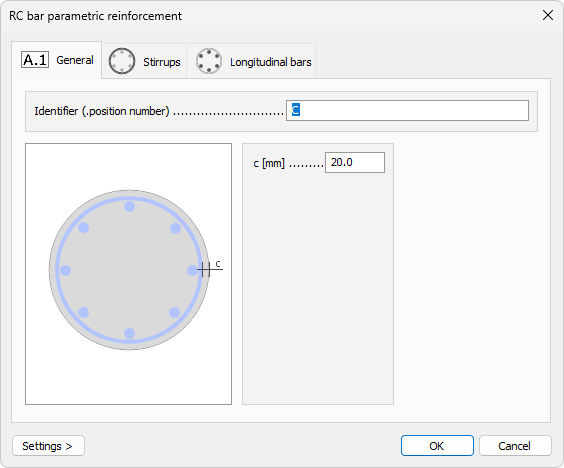
-
Identifier – text field for a user-defined reinforcement setup name
-
c – single numeric field for concrete cover
Stirrups tab
The Stirrups tab is identical to the Stirrups tab described above for Rectangular bar settings.
Longitudinal bars tab
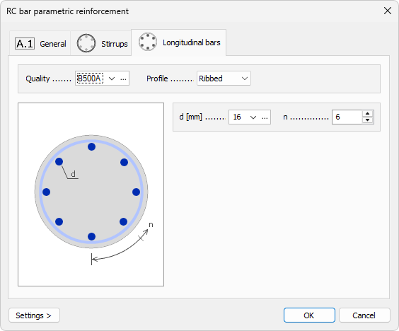
Top part
-
Quality – drop-down menu for longitudinal bar steel quality, with an Edit library button
-
Profile – drop-down menu with Ribbed and Smooth options
Bottom part
The left side shows a cross-section image with designators, and the right side contains parameters.
-
d – drop-down menu for longitudinal bar diameter, with an Edit library button
-
n – numeric field for number of longitudinal bars in the section