Fictitious shell
Use the Fictitious shell tool to add custom-volume plate elements that transmit forces without adding stiffness where you do not want it.
![]()
When you select Fictitious shell, a tool palette opens.

Main tools
- Define – draw a new fictitious shell with the current area-definition settings
- Properties – check or edit properties of existing fictitious shells. Opens the Default settings dialogue for the selected elements
- Convert – turn selected regular shells into fictitious shells
- Hole – cut an opening inside an existing fictitious shell
- Edge connections – define edge interaction and end behavior (read more below)
- Default settings – set the default parameters for new fictitious shells (read below in more detail)
Contour definition methods
Available for both Define and Hole tools.
- Rectangular – draw a rectangular contour
- Circular – draw a circular contour
- Polygonal – draw a custom polygon
- Pick lines – select lines from the model to define the shape
Only available with Define tool:
- Pick existing region – reuse an existing region’s shape
Connection tools
- Setup > – opens a dialogue for editing edge connection properties and endpoint behavior
- Presets > – opens a list of previously saved edge connection setups created using the Setup dialogue
note
The content of the Setup dialogue is the same as for other plate and wall elements.
To read more, see:
User interface ➔ Tab menus ➔ Structure ➔ Additional dialogues ➔ Shell Default Connections
Edge connection functions
Available when the Edge connection tool is selected.
- Edge connection properties – select an edge of a shell to view or edit connection settings
- Endpoint behavior – define how the ends of a shell's edge connect or terminate
note
To read more about these settings, see the relevant topics below:
- For Edge connection properties see:
User interface ➔ Tab menus ➔ Structure ➔ Additional dialogues ➔ Edge connections - For Endpoint behavior see:
User interface ➔ Tab menus ➔ Structure ➔ Additional dialogues ➔ Endpoint behaviour
Default settings
When you press the Default settings button, a dialogue window opens.
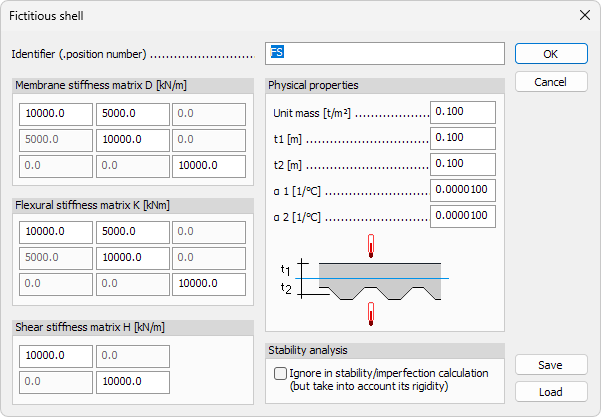
- Identifier – label shown in schedules, lists and tooltips
- Membrane stiffness matrix D – in-plane axial and shear stiffness. Use the numeric values for Dxx, Dyy, Dxy and DGxy
- Flexural stiffness matrix K – out-of-plane bending and torsional stiffness. Use the numeric values for Kxx, Kyy, Kxy, KGxy
- Shear stiffness matrix H – transverse shear stiffness. Use the numeric values for Hxz, Hyz
info
In order to have a stable stiffness matrix the following formulas needs to be true:
- Dxx*Dyy – Dxy*Dyx > 0
- Kxx*Kyy – Kxy*Kyx > 0
Physical properties
- Unit mass – mass per unit area. Keep at 0 for a weightless diaphragm
- t1 – thickness above mid-surface
- ɑ 1 – thermal expansion coefficient above element
- ɑ 2 – thermal expansion coefficient below element
Stability analysis
- Ignore in stability / imperfection calculation (but take into account its rigidity) – if selected, the shell’s stiffness is kept in the global model but its own stability modes are excluded from buckling or imperfection checks