Fictitious bar
Use the Fictitious bar tool to insert a custom-mass, zero-volume bar that transmits forces or releases degrees of freedom without adding stiffness where you do not want it.
![]()
When you select Fictitious bar, a tool palette opens.

Main tools
- Define – draw a new fictitious bar with the current direction and line-definition settings
- Properties – check or edit properties of existing fictitious bars. Opens the Default settings dialogue for the selected elements
- Convert – turn selected regular bars into fictitious bars
- Default settings – set the default parameters for new fictitious bars (read below in more detail)
Direction methods
Only available while Define tool is selected
- Predefined direction – align the local y′ axis of the bar to a standard reference
- Global coordinate system – orient y′ to global X, Y or Z
- User coordinate system – orient y′ to UCS x, y or z
- Local system – define a custom orientation by picking an auxiliary point or element
Line definition methods
- Straight line – pick two points to draw a straight bar
- Arc by center, start point and angle – define the centre, a start point and sweep angle
- Arc by 3 points – define three points on the arc
- Arc by start, end point and tangent – define start and end points plus the tangent at start
- Line by selection – select an existing line or edge to define the fictitious bar path
Default settings
When you press the Default settings button, a dialogue window opens.
This dialogue contains two tabs: General and End conditions.
General tab
On the General tab, you can select fictitious bar mode. Some parameters are available for only one mode.
Overall settings
These parameters are available in both fictitious bar modes.
- Identifier – Label used in schedules and tooltips
- Unit mass – Mass per unit length. Leave at 0 for a weightless link
Below the identifier are three buttons:
-
Normal – default mode. The fictitious bar can carry axial, shear, bending and torsion. Uses linear elastic material model
-
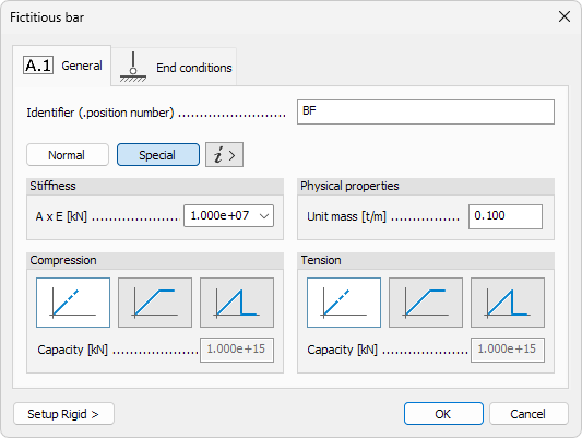
Special – tension/compression-only link. No shear, bending or torsion. Uses linear elastic model with optional capacity limits
-
i > – information button that summarises the differences between Normal and Special modes
Special bars work similar to Trusses and can be loaded only at nodes. These are ideal for elements such as tie-rods, stringers or panel anchors that must transmit pure axial force without bending.
Parameters available in Normal mode
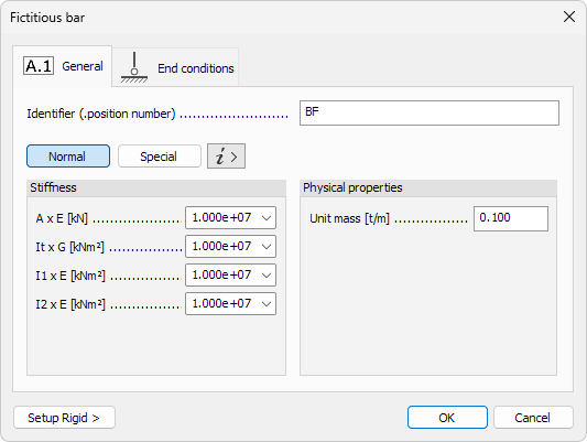
- A × E – axial stiffness
- It × G – torsional stiffness
- I1 × E – bending stiffness about principal axis 1
- I2 × E – bending stiffness about principal axis 2
Parameters available in Special mode
-
A × E – axial stiffness (tension & compression)
-
Mode – behaviour under tension or compression
- Elastic – no capacity limit; force-deformation remains linear
- Plastic – force is capped by a limit value; stiffness after yielding is zero
- Brittle – force is capped by a limit value; the element is removed from calculation once the limit is exceeded
-
Limit force – maximum axial force the member can carry. Available only when Plastic or Brittle mode is selected
End conditions tab
These follow standard practices for any bar object.
To read more about End conditions tab, see the topic below:
User interface ➔ Tab menus ➔ Structure ➔ Additional dialogues ➔ Bar End conditions