Truss member
Use the Truss member tool to define axial-only structural elements typically used in trusses, tension systems or braced frames. Truss elements can have plastic limits in analysis.
![]()
When you select Truss member, a tool palette opens.

Main tools
- Define – create a new truss member using direction and placement methods
- Properties – check or edit parameters of an existing truss member. Opens the Default settings dialogue for the selected elements
- Convert – convert existing wall foundation, beam, column, fictitious bar and some compatible solid shape elements into trusses
- Physical alignment – adjust the vertical placement of the truss member relative to its reference line
- Default settings – set default parameters for geometry, material, section, and stiffness (read below in more detail)
To read more about the Physical alignment, see the topic:
User interface ➔ Tab menus ➔ Structure ➔ Additional dialogues ➔ Physical alignment
Directional functions
Available when the Define tool is selected.
- Predefined direction – define the truss member along the default direction
- Parallel with line – select an existing line and place the truss member parallel to it
- Perpendicular to plane – select a plane to place the truss member normal to its surface
- Direction – only available with Predefined direction. Use to select one of five direction modes:
- y′ axis is parallel to global XY, YZ, or XZ plane
- y′ axis is parallel to UCS
- y′ axis is perpendicular to UCS
Placement methods
Available when the Define tool is selected.
- Straight line – draw a straight truss member between two points
- Line by selection – select an existing edge or line element to define the truss path
Default settings dialogue
When you press the Default settings button, a dialogue window opens.
This dialogue contains five tabs: General, Section, Material and Stiffness. These follow the settings used in regular bar elements, except for the General tab, which is specific to truss members.
General tab
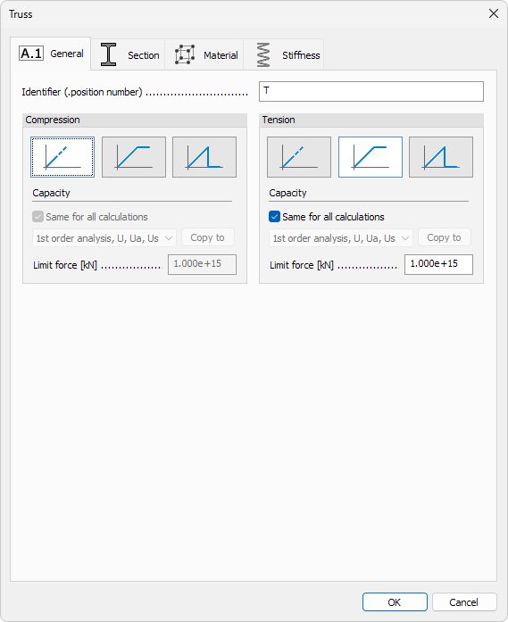
Identifier
- Identifier – label shown in schedules, lists, and tooltips
- Mode – behaviour under tension or compression
- Elastic – no capacity limit; force-deformation remains linear
- Plastic – force is capped by a limit value; stiffness after yielding is zero
- Brittle – force is capped by a limit value; the element is removed from calculation once the limit is exceeded
Capacity
-
Same for all calculations – when ticked, the same capacity apply to every analysis
-
Calculation type – drop-down list available when the box is unticked
-
Copy to – copies the current settings to one or more calculation types
-
Limit force – maximum axial force the member can carry. Available only when Plastic or Brittle mode is selected
Section, Material, Stiffness tabs
Content of other tabs follow the settings used in regular bar elements.
To read more about these settings, see the relevant topics below:
- For Section tab:
User interface ➔ Tab menus ➔ Structure ➔ Additional dialogues ➔ Bar Section - For Material tab:
User interface ➔ Tab menus ➔ Structure ➔ Additional dialogues ➔ Regular Material - For Stiffness tab:
User interface ➔ Tab menus ➔ Structure ➔ Additional dialogues ➔ Bar Stiffness