Shell General
Shell General
The Shell - General dialogue defines basic geometric and material parameters for various shell elements. Tools that use the same or similar dialogues include:
- Plane plate, Plane wall
- Profiled plate, Profiled wall
- Timber plate, Timber wall
- Simple retaining wall
- Foundation slab
- Shell model of Beam and Column
Depending on the shell type, the General tab may have different elements, but they all are similar.
When you open the General tab, the following (or similar) window appears.
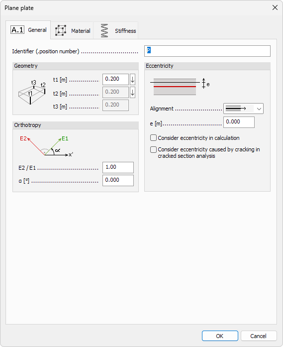
Common parameters
- Identifier – label shown in schedules, lists, and tooltips
Eccentricity
- Alignment – drop-down list to place the analytical mid-surface relative to the physical thickness
- Top/Left
- Center
- Bottom/Right
- e – numeric offset for custom eccentricity (positive along local z′)
- Consider eccentricity in calculation – include e when assembling stiffness matrix
- Consider eccentricity caused by cracking in cracked section analysis – adjust eccentricity automatically when the element is analysed in a cracked state
Plane shell additional settings
Settings that are available in plane shell dialogues.
Geometry
Enter thickness values for constant or tapered shells.
- t1 – thickness at the reference point (or uniform thickness when the shell is constant)
- t2 – second reference thickness (variable-thickness shells)
- t3 – third reference thickness (variable-thickness shells)
Orthotropy
Define in-plane material ratios for orthotropic behaviour.
- E2 / E1 – ratio of stiffness in local y′ to stiffness in local x′
- α – principal angle (°) between material axes and local x′
Profiled shell additional settings
For Profiled plate and Profiled wall, the dialogue contains all the common parameters, plus the following additional settings.
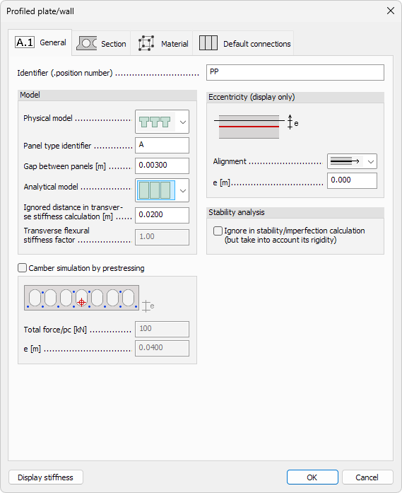
Model
- Physical model – drop-down list with options: In situ, Prefabricated
- Panel type identifier – free text field for naming or numbering panel types
- Gap between panels – numeric field defining spacing between adjacent panels
- Analytical model – drop-down list with options: Continuous, Panel
- Ignored distance in transverse stiffness calculation – numeric field
- Transverse flexural stiffness factor – reduction factor
To read more about the transverse stiffness calculation, read the relevant support article:
Camber simulation
- Camber simulation by prestressing – checkbox to activate camber simulation
- Total force / pc – prestressing force applied per panel
- e – eccentricity of the prestressing force (see accompanying section image)
Stability analysis
- Ignore in stability / Imperfection calculation (but take into account its rigidity) – checkbox to exclude the panel from stability checks while still considering its stiffness
At the bottom of the dialogue window:
- Display stiffness – display the stiffness matrix window (read below in more detail)
Timber shell additional settings
For Timber plate and Timber wall, the dialogue contains all the common parameters, plus the following additional settings.
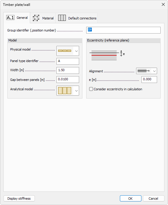
Model
- Physical model – drop-down list with options: Continuous, Panel
- Panel type identifier – free text field for naming or numbering panel types
- Width – numeric field defining panel width
- Gap between panels – numeric field defining spacing between adjacent panels
- Analytical model – drop-down list with options: Continuous, Panel
At the bottom of the dialogue window:
- Display stiffness – display the stiffness matrix window (read below in more detail)
Display stiffness
When you press Display stiffness button in the bottom of profiled shell or timber shell dialogue window, a new dialogue opens. In this dialogue you can see stiffness matrix values for flexural, membrane, shear, eccentricity (coupling) and additional parameters about the shell. Depending on the shell type, not all the data is available.
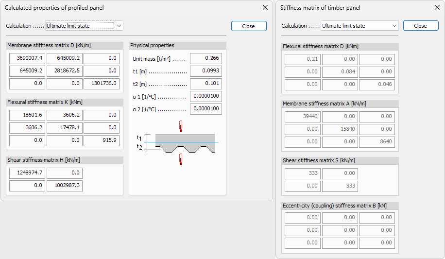
- Calculation – use the dropdown menu to see the stiffness values for different analysis modes