Edge connections
Many structural elements in FEM-Design can be connected to other parts of the structure using connection-type objects. These define how loads are transferred, how supports behave, or how two objects interact. All of these tools share the same core logic and structure in their settings. However, depending on the tool, some parts of the dialogue may be simplified — for example, only certain degrees of freedom may be editable, or some options may be hidden altogether. Following tools use similar dialogues:
| Edge connection | Support tools | Connection tools |
|---|---|---|
| Foundation slab | Point support | Point connection |
| Retaining wall | Point support group | Line connection |
| Plane wall | Line support | Surface connection |
| Profiled wall | Line support group | |
| Timber wall | Surface support | |
| Plane plate | Stiffness point (inside surface support tool) | |
| Profiled plate | ||
| Timber plate | ||
| Fictitious shell |
Connection dialogue
This dialogue has two tabs: General and Data.
General tab
- Identifier – optional name or label for the edge connection
Data tab
Contains all the connection settings for how the connection interacts with adjacent elements.
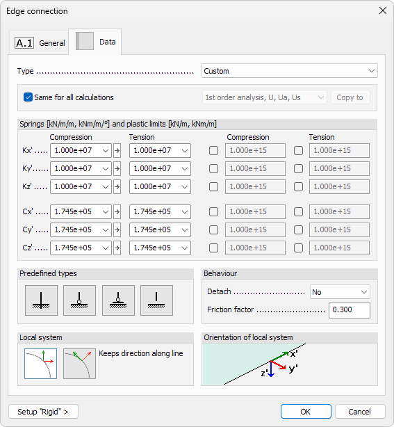
Type
Type – use drop-down list to choose a predefined named connection type from the library. These named types are saved connection presets that can be reused across different objects.
Selecting the Edit library... option in the drop-down list opens a new dialogue for modifying the connection library (read below in more detail)
Calculations
Use these options to controls whether the same connection parameters are applied to all analysis types or different ones can be defined individually.
- Same for all calculations – when checked, the connection uses the same spring and plastic settings for all calculations
- Calculation type – drop-down list that available when the checkbox is unchecked. Lets you select a specific calculation type and define unique parameters for each
- Copy to – copies the settings from the current calculation type to one or more other calculation types
Springs
Define the linear stiffness and plastic limits for the available degrees of freedom in the connection.
Each degree of freedom includes:
- Compression and Tension stiffness - numeric input fields for spring stiffness. There is also a drop-down menu to select either of the predefined values: Fixed or Free
- Plastic limit – optional yield force limit for the spring. Use the checkbox to enable plasticity limit and enter the value
Depending on the tool and connection type, the available degrees of freedom may include:
- Kx′, Ky′, Kz′ – translational springs and plastic limits along local axes
- Cx′, Cy′, Cz′ – rotational springs and plastic limits about local axes
There is an arrow button between the compression and tension values. If the button is active (light background) then writing a value into compression field fills the same value to tension field. If the button is inactive (dark background) then writing the value into compression field will not overwrite the value in the tension field.
The compression value will never be filled backward when writing into the tension field, no matter the state of the button.
Predefined types
Use these buttons to quickly apply a standard set of spring values based on typical structural behaviour.
Available options are:
- Fixed – sets high stiffness in all directions
- Hinged – releases rotational stiffness while keeping translational stiffness
- Free in z′ direction – zero stiffness only in vertical direction (Kz′), other directions remain fixed
- Free – releases all degrees of freedom
Selecting one of these options will overwrite all manually entered stiffness and plastic values. Use them as a quick starting point, then fine-tune if needed.
Behaviour
Use the options to define how the connection behaves in case of relative movement between connected elements.
- Detach – drop-down list to select the local axis (x′, y′ or z′ in both compression and tension directions) along which the connection may open or lose contact
- Friction factor – numeric value that defines sliding resistance along the local x' direction
When the detach behaviour is selected for an axis and direction, then if a force is acting in that direction, the whole connection is detached - so it does not connect to any other direction either.
In contrast, setting one degree of freedom to free will just make it have infinite deformation in that direction, but all the other directions remain intact and can still transfer loads.
Local system
Choose how the local coordinate system of the connection is aligned along the geometry.
- Keeps direction along line – the local system (x′, y′, z′) maintains a constant direction along the connected edge or element. This option should be used for straight line edges
- Direction changes along line – the local system rotates with the element’s geometry, adapting to its curvature or orientation. This option is best suited for curved edges, as the settings will be applied longitudinal/perpendicular to each point on the curved edge
These settings affect how the spring directions and detaching behaviour are interpreted along the object.
Orientation of local system
This section shows a visual diagram of the local coordinate system (x′, y′, z′) used by the connection.

The image helps clarify which direction corresponds to which spring or detaching behaviour in the Springs and Behaviour sections. No user input is required here - the section is informational only.
Interface position
This section is available only in Point connection and Line connection dialogues. It sets the exact location along the connection element where the springs, detaching, and friction parameters are applied.

- r – single numeric field for Point connection. Enter a value between 0 - 1 to specify the proportion measured from the element’s start point.
- rs / re – two numeric fields for Line connection.
- rs – ratio at the start of the line
- re – ratio at the end of the line
A value of 0 locates the interface at the start point, 1 at the end point, and any value in between positions it proportionally along the element.
Setup "Rigid" ›
If you click on the Setup "Rigid" › button at the bottom of the dialogue, a new dialogue window opens.

Here you can quickly assign very high stiffness values to simulate a perfectly rigid connection.
- Motions – translational stiffness applied to all K-springs (x′, y′, z′)
- Rotations – rotational stiffness applied to all C-springs (x′, y′, z′)
Edit library dialogue
Selecting Edit library… from the Type drop-down opens a dedicated window for creating, modifying, and organising named connection types.
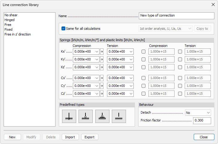
Left pane - library list
A scrollable list shows every saved connection type.
Click a name to load its parameters into the right-hand controls.
Right pane - parameters
- Name – text field displaying the selected connection’s name. Enter a new label here when creating a type.
There are also parameters for the connection which are identical to the descriptions above in the main article. These include:
- Calculations
- Springs
- Predefined types
- Behaviour
Bottom-row actions
- New – adds the current values and Name as a new type to the library
- Modify – overwrites the selected type with the current settings
- Delete – removes the highlighted type from the library
- Import – load an external file library file. Entries with matching names will be ignored, keeping the local definitions
- Export – save the entire library to an external file for backup or sharing