Moving load
Moving load
Use Moving load tool to define a general load pattern for single vehicle or group of loads (over-head cranes etc.)
![]()
When you select the Moving load, a new tool palette opens.

Main tools on the tool palette
- Define – add a new moving load to the model
- Properties – check properties of existing moving loads. This will open the Default settings dialogue for the selected load(s)
- Vehicle – create new vehicle from existing loads on model and insert that vehicle into database (read below in more detail)
- Vehicle position – add, remove or change vehicle positions on the existing moving load (read below in more detail)
- Animate motion – see the loads moving in animation (read below in more detail)
- Default settings – change some settings (read below in more detail)
Types of moving loads
Only available with Define or Properties functions.
- Line moving load – draw or select a path where the load will be moving on
- Surface moving load – draw or select an area where the load will be moving on
Defining loads paths, areas and action points
When you select the Define tool, you can add new load paths or areas to the model
Line tools and parameters
Line tools are only available with Line moving load functions.
- Draw path – draw a path using straight lines
- Select path – select a path based on any existing line or edge
- Name – set a name for the moving load
- Divide the path into load action points by dividing it into sections. Two options are available:
- By division number – select the number of divisions
- By distance – select the length of one division
Contour tools and parameters
Contour tools are only available with Surface moving load functions.
- Rectangular – define a rectangle by two opposing corner points
- Circular – define a circle by center point and radius
- Polygonal – define the polygon with multiple consecutive points
- Pick lines – define the shape by using any existing closed shape that is made of lines, edges, axis or edges of a Region
- Pick existing region – define shape by selecting an existing Region
- Name – set a name for the moving load
- Divide the surface area into load action points by setting up the point-grid parameters:
- Grid x' – distance between the points in local x-direction
- Grid y' – distance between the points in local y-direction
- Edge x' – distance of the first row of points from the edge of the area in local x-direction
- Edge y' – distance of the first row of points from the edge of the area in local y-direction
Creating vehicles from existing loads
Use the Vehicle tool to convert existing loads into a reusable vehicle definition.
When you activate the Vehicle tool, you need to select loads from the model, define the origin point and the local coordinate system directions for the vehicle. You can also turn on Delete original loads option on the toolbar, which will remove the selected loads from the model once the vehicle is created.
After you have set the directions Vehicle database dialog will open.
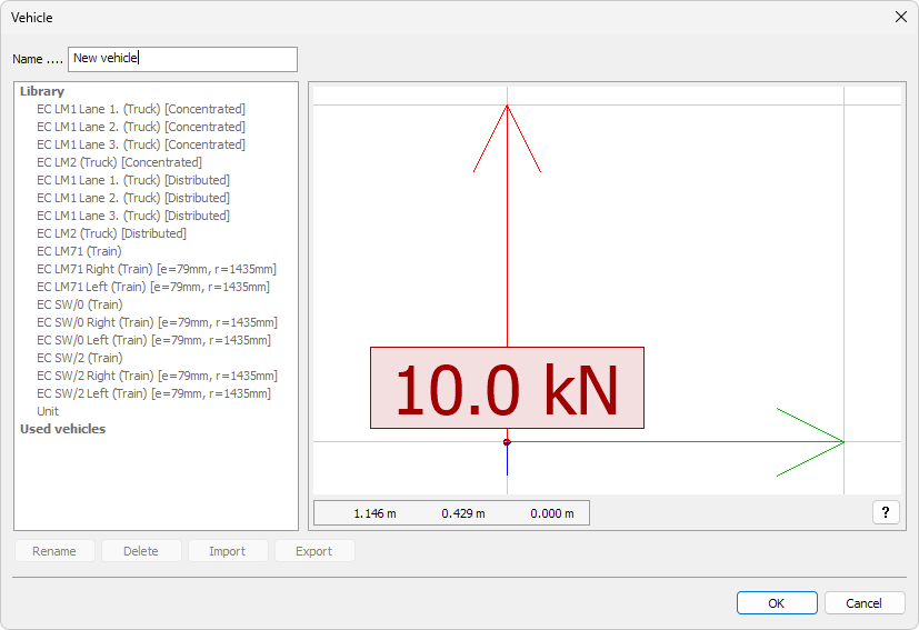
On the left hand side you can view a list of all saved vehicles. You can also set a name for the current vehicle:
- Name – set name for the current vehicle
On the right hand side you can see the loads for your currently created vehicle. You can pan and orbit the view to make sure you have the correct loads. Under the graphical window, you can see coordinates and a question mark button
- ? – use it to see the shortcuts for navigating the view
There are other buttons on the dialogue window, but they are disabled while you define new vehicles. Read below about all the other functions of the Vehicle database.
Managing vehicle positions
Use the Vehicle position tool to manage how and where a vehicle moves along a defined path or area.

- Add – insert new position points to the moving load
- Delete – remove selected positions from the moving load
- Move – adjust the location of a position point on the path or area
- Reset - Select paths – revert all modifications and restore the moving load to its default state
Animating vehicle motion
Use the Animate motion tool to preview how the moving load travels along its defined path or area.

You can control the playback using the Speed slider.
Default settings
The Default settings tool opens a new dialogue window. This dialogue window has multiple tabs.
General
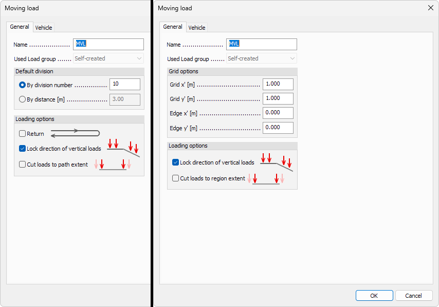
Options on this tab depend on whether you selected Line moving load or Surface moving load option before opening the dialogue.
Options available for both type of loads:
-
Name – set a name for the moving load
-
Used load group – use the dropdown menu to select into which load group the generated moving load will be added. The list contains suitable available groups. There is also one special selection:
- Self-created - use this option to allow the tool to create new load group automatically
-
Loading options - select how the load will be applied:
- Lock direction of vertical loads – select to keep loads vertical all the time. If unselected, then the vertical load direction will follow the path/region normal direction.
- Cut loads to path extent or Cut the loads to region extent – select to remove any parts of the load that is overhanging the path or the region
Options for Line moving load
-
Default division – division will divide the path and area into load action points. You can select which division method you want to use as default. Two options are available:
- By division number – select the number of divisions
- By distance – select the length of one division
-
Loading options - select how the load will be applied:
- Return – select if you want the load to make a round-trip
Options for Surface moving load
- Grid options – divide the surface area into load action points by setting up the point-grid parameters:
- Grid x' – distance between the points in local x-direction
- Grid y' – distance between the points in local y-direction
- Edge x' – distance of the first row of points from the edge of the area in local x-direction
- Edge y' – distance of the first row of points from the edge of the area in local y-direction
Vehicle
The Vehicle tab contains the similar dialogue as in the Vehicle command for adding new vehicles.
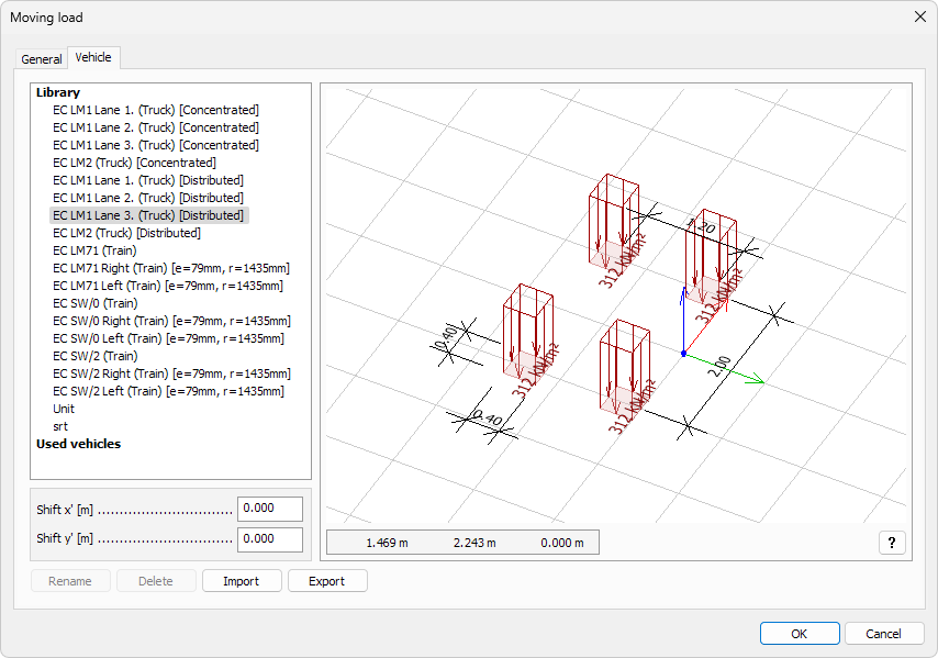
On the left hand side you can view a list of all saved vehicles.
Below the list are parameters for shifting the insertion point relative to the local origin of the vehicle:
- Shift x' – shift the local x-direction of the vehicle
- Shift y' – shift the local y-direction of the vehicle
On the right hand side you can see the loads for currently selected vehicle. You can pan and orbit the view to make sure you have the correct loads. Under the graphical window, you can see coordinates and a question mark button
- ? – use it to see the shortcuts for navigating the view
At the bottom of the dialogue window, you can see four buttons:
- Rename – rename the selected vehicle if possible (only available for user-created vehicles)
- Delete – delete the selected vehicle
- Import – import the vehicle database from a file. Entries with matching names will be ignored, keeping the local definitions
- Export – export the vehicle database to a file