Line load
Use the Line load tool to add line force or moment to the model.
![]()
When you select the Line load tool from the panel, a new tool palette opens.

Main tools on the tool palette
| Description | |
|---|---|
| Use Define tool to add a new line load to the model. | |
| Use Properties tool to check properties of existing line loads. This will open the Default settings dialogue for the selected load(s). | |
| Use Info tool to see additional info on existing line loads. This will open the Line load info dialogue for the selected load (read below in more detail). | |
| Use q1 numeric field to enter the value of the force at the load's start. Only available when defining load as Force. | |
| Use q2 numeric field to enter the value of the force at the load's end. Only available when defining load as Force. | |
| Use m1 numeric field to enter the value of the moment at the load's start. Only available when defining load as Moment. | |
| Use m2 numeric field to enter the value of the moment at the load's end. Only available when defining load as Moment. | |
| Use F numeric field to enter the value of the resultant force. Only available when defining load as Force by resultant. | |
| Click on the down arrow button next to a numeric field to activate or deactivate the automatic numeric field filling function. When the function is active, program will automatically fill the next numeric field with the same value, while you enter a value in the current field. Active function's arrow background is marked with light color. Inactive function's arrow background is marked with dark color. Function is active by default. | |
 | Use Default settings tool to change some settings (read below in more detail). |
Automatic numeric field filling function does not prevent you from manually entering a different value in the automatically filled field. It is just a helping function to fill in the values faster.
Force or moment
| Description | |
|---|---|
| Use Force function to define a load as force. | |
| Use Moment function to define a load as moment. | |
| Use Force by resultant function to define a load as force by defining it's resultant. |
Direction tools
| Description | |
|---|---|
| Use Predefined direction function to select the load direction from 6 possible options. | |
| Use Parallel with line function to set the load direction by drawing a line in the model space. | |
| Use Perpendicular to plane tool to set the load direction to be perpendicular to a selected plane. You can select the plane in the model space. | |
| Use Object's local system tool to select the load direction from 3 possible options. | |
| Only while Predefined direction tool is selected, use this Direction tool to select one of the 6 possible options - global coordinate system X, Y or Z axis or user coordinate system x, y or z axis. | |
| Only while Object's local system tool is selected, use this Direction tool to select one of the 3 possible options - direction parallel to local x', y' or z' axis. | |
| Only while Predefined direction tool or Object's local system tool is selected, use the Positive direction and Negative direction buttons to change positive/negative direction of the selected axis or normal of the selected plane. |
Line tools
Only available for the Predefined direction, Parallel with line or Perpendicular to plane directions.
| Description | |
|---|---|
| Use Straight line function to define load as a straight line. | |
| Use Arc by center, start point and angle function to define load as an arc by center point, start point and angle of the arc. | |
| Use Arc by 3 points function to define load as an arc by defining it with 3 points: start, end and middle of the arc. | |
| Use Arc by start, end point and tangent function to define load as an arc by its start point, endpoint and start tangent. | |
| Use Line by selection function to define load as a line based on any existing line or edge. |
Other tools
| Description | |
|---|---|
| Use Assign to structure tool to assign the load to a structural element already while defining the load. |
To read about assigning the load to structure see the topic
User interface ➔ Tab menus ➔ Loads ➔ Panel Modify ➔ Assign load to structure
Line load info dialogue
The Info tool opens a new dialogue window depending on whether Force, Moment or Force by resultant function is selected.
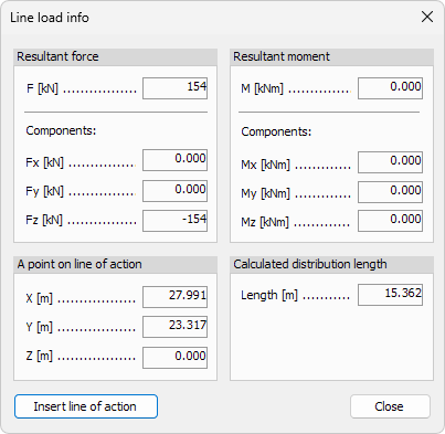
When Force or Force by resultant function is selected this dialogue opens:
When Moment function is selected this dialogue opens:

Resultant force
- F – Resultant force value.
- Fx – resultant force vector's component in global X direction.
- Fy – resultant force vector's component in global Y direction.
- Fz – resultant force vector's component in global Z direction.
A point on line of action
-
x – resultant force location coordinate in global X direction.
-
y – resultant force location coordinate in global Y direction.
-
z – resultant force location coordinate in global Z direction.
-
Insert line of action – use this button to insert a line into the model that represents the resultant force. It will be inserted in the location described with above coordinates.
Resultant moment
- M – resultant moment value.
- Mx – resultant moment vector's component in global X direction.
- My – resultant moment vector's component in global Y direction.
- Mz – resultant moment vector's component in global Z direction.
Calculated distribution length
- Length – see the length of the line load.
Default settings
The Default settings tool opens a new dialogue window depending on whether Force, Moment or Force by resultant function is selected.
When Force function is selected this dialogue opens:

When Moment function is selected this dialogue opens:

When Force by resultant function is selected this dialogue opens:

| Tools and functions in the dialogue windows | |
|---|---|
| q1 | Change the value of the force at the load's start. Only available when defining load as Force. |
| q2 | Change the value of the force at the load's end. Only available when defining load as Force. |
| m1 | Change the value of the moment at the load's start. Only available when defining load as Moment. |
| m2 | Change the value of the moment at the load's end. Only available when defining load as Moment. |
| F | Change the value of the resultant force. Only available when defining load as Force by resultant. |
| Load case | Select a load case for the load |
| Comment | Add a comment to the load |
| Select the Apply on the eccentric axis/surface if you want to apply the load on an eccentric axis of eccentric surface of a structural element. If unselected, the load is applied on the centroid axis. Only available when defining load as Force or Force by resultant. | |
| Select to apply the load intensity along the action line (for example, dead load). | |
| Select to apply the load intensity perpendicular to the direction of the load (for example, snow load). | |
| Select to apply the load so, that the direction of the load is always constant along the action line (for example, dead load or snow load). | |
| Select to apply the load so, that the direction of the load varies along the action line. The characteristic load direction is in the middle point of the load. |