Shell deflection region
The Shell deflection region tool is used to define regions on shell elements that are used for evaluating deflections in deflection checks.
![]()
When you activate this tool, a tool palette opens.

Main tools
- Define – create new shell deflection regions using contour definition methods
- Properties – view or edit properties of existing shell deflection regions. Opens the Default settings dialogue for the selected regions
- Reference plane – define or modify the reference plane used for the deflection region
- Reset – reset the reference plane and region settings to default behaviour
- Default settings – open the default settings dialogue for shell deflection regions (read below in more detail)
Contour definition methods
Available when Define is selected.
- Rectangular – draw a rectangular deflection region
- Circular – draw a circular deflection region
- Polygonal – draw a custom polygonal deflection region
- Pick lines – define the region by selecting existing lines or edges
- Pick existing region – reuse the contour of an existing shell or region
Reference plane functions
Available when Reference plane is selected.
- Cantilever mode – define the region as a cantilevered shell area for deflection evaluation
- Fitting to three point – define the reference plane by selecting three points
Default settings
When you press Default settings, a dialogue window opens where you can define checking criteria, characteristic length and deflection limits for shell deflection regions.
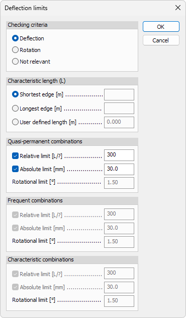
Checking criteria
Select which type of check is performed for the shell deflection region:
- Deflection – evaluate vertical or out-of-plane deflection
- Rotation – evaluate rotational deformation
- Not relevant – exclude the region from deflection checks
Characteristic length (L)
Define how the characteristic length used for relative limits is determined:
- Shortest edge – use the shortest edge length of the region
- Longest edge – use the longest edge length of the region
- User defined length – manually define the characteristic length
Deflection limits
Deflection limits can be defined separately for different SLS load combination types.
Available options depend on the selected combination type.
For each combination type, the following limits can be used:
- Relative limit – limit deflection relative to the characteristic length
- Absolute limit – limit deflection using an absolute value
- Rotational limit – limit rotation of the shell region
The defined limits are used when running the deflection check with the Check tool.
Only load combination types enabled in the Configure deflection check tool are available in this dialogue.
To read more about the Configure deflection check tool, see the topic:
User interface ➔ Tab menus ➔ Analysis ➔ Panel Deflection check ➔ Configure deflection check